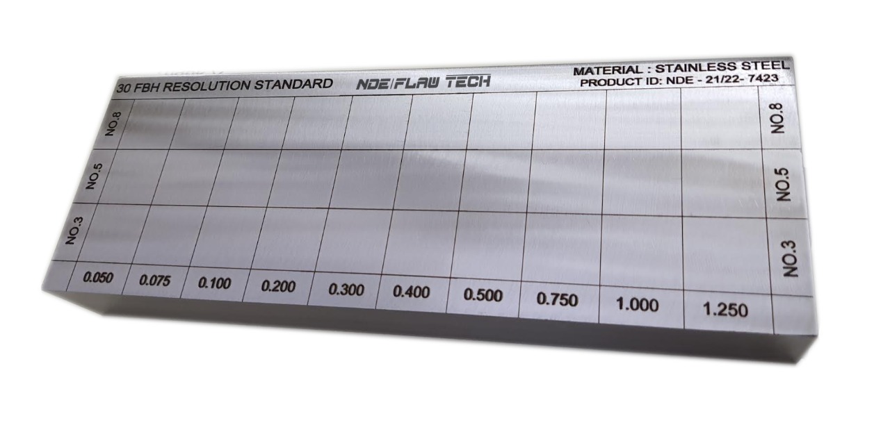
30 FBH Resolution Reference Block
The 30 FBH resolution reference block is used to evaluate the near-surface resolution and flaw size/depth sensitivity of a normal-beam setup. In accordance with ASTM E428.

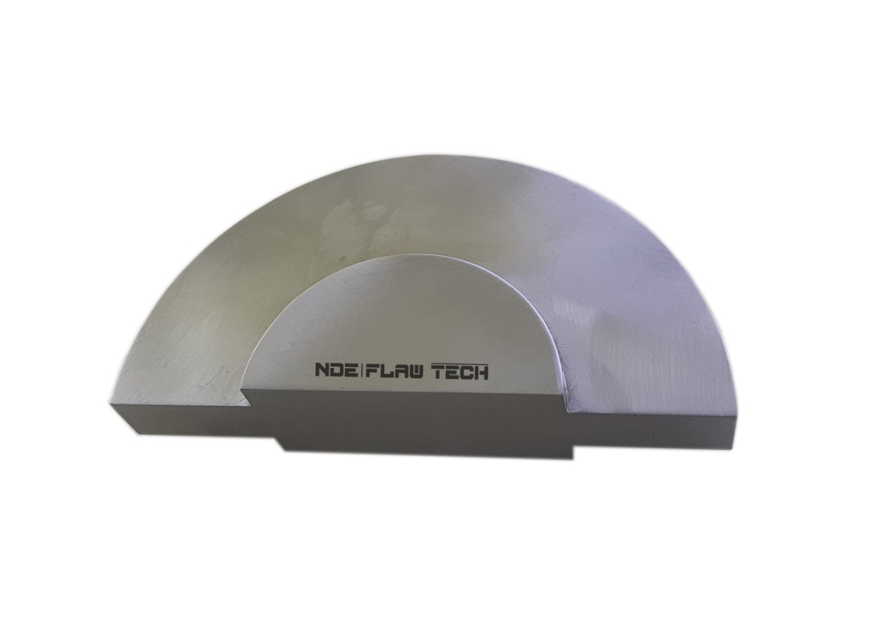
90° Curved 5-Step Block
90° Curved 5-Step Block For thickness and linearity calibration of curved surfaces. Inch Version: This 90° Curved 5-Step block is machined from a solid 2" diameter bar with step thicknesses of .100", .200", .300", .400" and .500". ID radius is a constant .50" / 1.00" diameter. Inch Block Curvature: 0.500" step has a 1.0" radius, 0.400" step has a 0.9" radius, 0.300" step has a 0.8" radius, 0.200" step has a 0.7" radius, and 0.100" step has a 0.6" radius.

ASME N-625 Reference Plate
ASME N-625 Reference Plate In accordance with ASME 1275N Boiler and Pressure Vessel Code, Section III, Nuclear Vessels. Used for longitudinal, shear, and surface wave sensitivity calibrations.
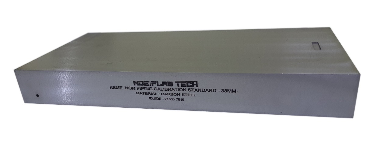
ASME Sec V Basic Calibration Block
ASME Sec V Basic Calibration Block This block can be used as a calibration block with a compression probe; however, its main use is as a reference block with either compression or shear wave probes. Its most common uses are for setting test sensitivity prior to inspection, using various depth of individual Side Drilled Holes (SDH) as reference reflectors. The test sensitivity as set by means of Distance amplitude Curve (DAC)/Time Correction Gain (TCG). The block size and reflector locations shall be adequate to perform calibrations for the beam angle(s) and distance range(s) to be used. The block thickness (T) shall be varying according to test object. Acoustic signals from the same reflecting surface will have different amplitudes at different distances from the transducer. Distance amplitude correction (DAC) provides a means of establishing a graphic ‘reference level sensitivity’ as a function of sweep distance on the A-scan display. The use of DAC allows signals reflected from similar discontinuities to be evaluated where signal attenuation as a function of depth has been correlated. Most often DAC will allow for loss in amplitude over material depth (time), graphically on the A-scan display but can also be done electronically by certain instruments. Because near field length and beam spread vary according to transducer size and frequency, and materials vary in attenuation and velocity, a DAC curve must be established for each different situation. DAC may be employed in both longitudinal and shear modes of operation as well as either contact or immersion inspection techniques. A distance amplitude correction curve is constructed from the peak amplitude responses from reflectors of equal area at different distances in the same material. A-scan echoes are displayed at their non-electronically compensated height and the peak amplitude of each signal is marked on the flaw detector screen or, preferably, on a transparent plastic sheet attached to the screen. Reference standards which incorporate side drilled holes (SDH), flat bottom holes (FBH), or notches whereby the reflectors are located at varying depths are commonly used. It is important to recognize that regardless of the type of reflector used, the size and shape of the reflector must be constant. Commercially available reference standards for constructing DAC include ASTM Distance/Area Amplitude and ASTM E1158 Distance Amplitude blocks, NAVSHIPS Test block, and ASME Basic Calibration Blocks
IIW-Type 2 Calibration Block
IIW-Type 2 Calibration Block IIW type blocks are used to calibrate instruments for both angle beam and normal incident inspections. Some of their uses include setting metal-distance and sensitivity settings, determining the sound exit point and refracted angle of angle beam transducers, and evaluating depth resolution of normal beam inspection setups. Instructions on using the IIW type blocks can be found in the annex of American Society for Testing and Materials Standard E164, Standard Practice for Ultrasonic Contact Examination of Weldments. A modified version of the original IIW-Type 1 design. Includes a 2.0" radius x .250" deep cut-out superposed on the 4.0" radius for distance calibration. Also includes numbers 3, 5 and 8 through holes (3/64", 5/64" AND 8/64" diameter) for sensitivity testing or surface wave inspection, and distance calibration marks to the 2.0" hole. In accordance with International Institute of Welding, ASTM E164 and U.S. Air Force NDI Manual T.O. 33B-1-1 specifications.

IIW-Type 1 Calibration Test Block
IIW-Type 1 Calibration Test Block IIW type blocks are used to calibrate instruments for both angle beam and normal incident inspections. Some of their uses include setting metal-distance and sensitivity settings, determining the sound exit point and refracted angle of angle beam transducers, and evaluating depth resolution of normal beam inspection setups. Instructions on using the IIW type blocks can be found in the annex of American Society for Testing and Materials Standard E164, Standard Practice for Ultrasonic Contact Examination of Weldments.
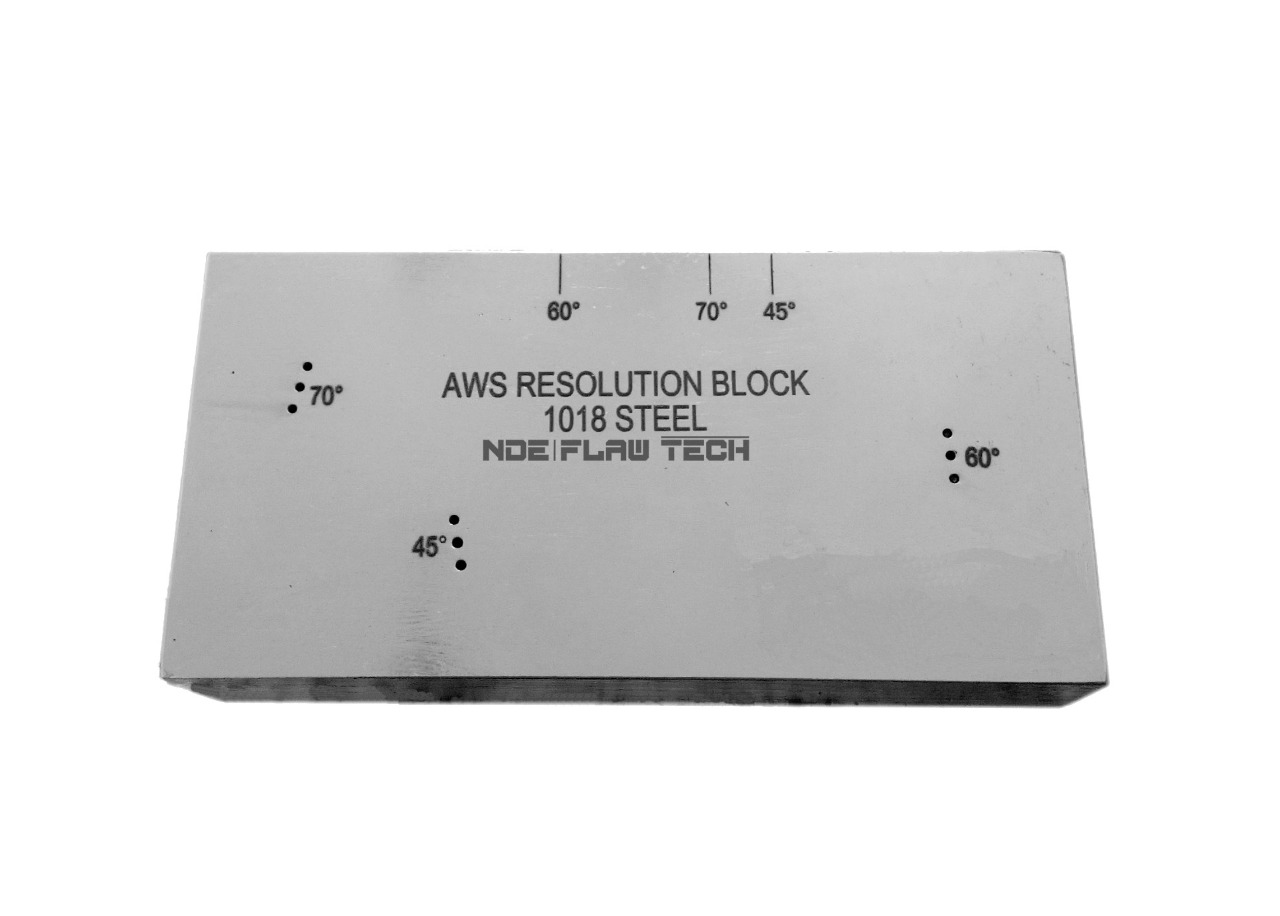
AWS Resolution Reference Test Block
AWS Resolution Reference Test Block Also called an RC block, the AWS Resolution Reference Block is used for checking resolution capabilities of angle beam transducers. Contains three sets of .0625" diameter through-holes for 45°, 60° and 70°. In accordance with AWS Welding Highway and Railway Bridges specification D2.0, and Structural Welding Code ANSI/AWS D1.1. AWS does not specify a separate metric version of the AWS Resolution block. The metric block in AWS shows only the metric equivalents to the standard design. Therefore, this one block can be used for both inch and metric requirements.
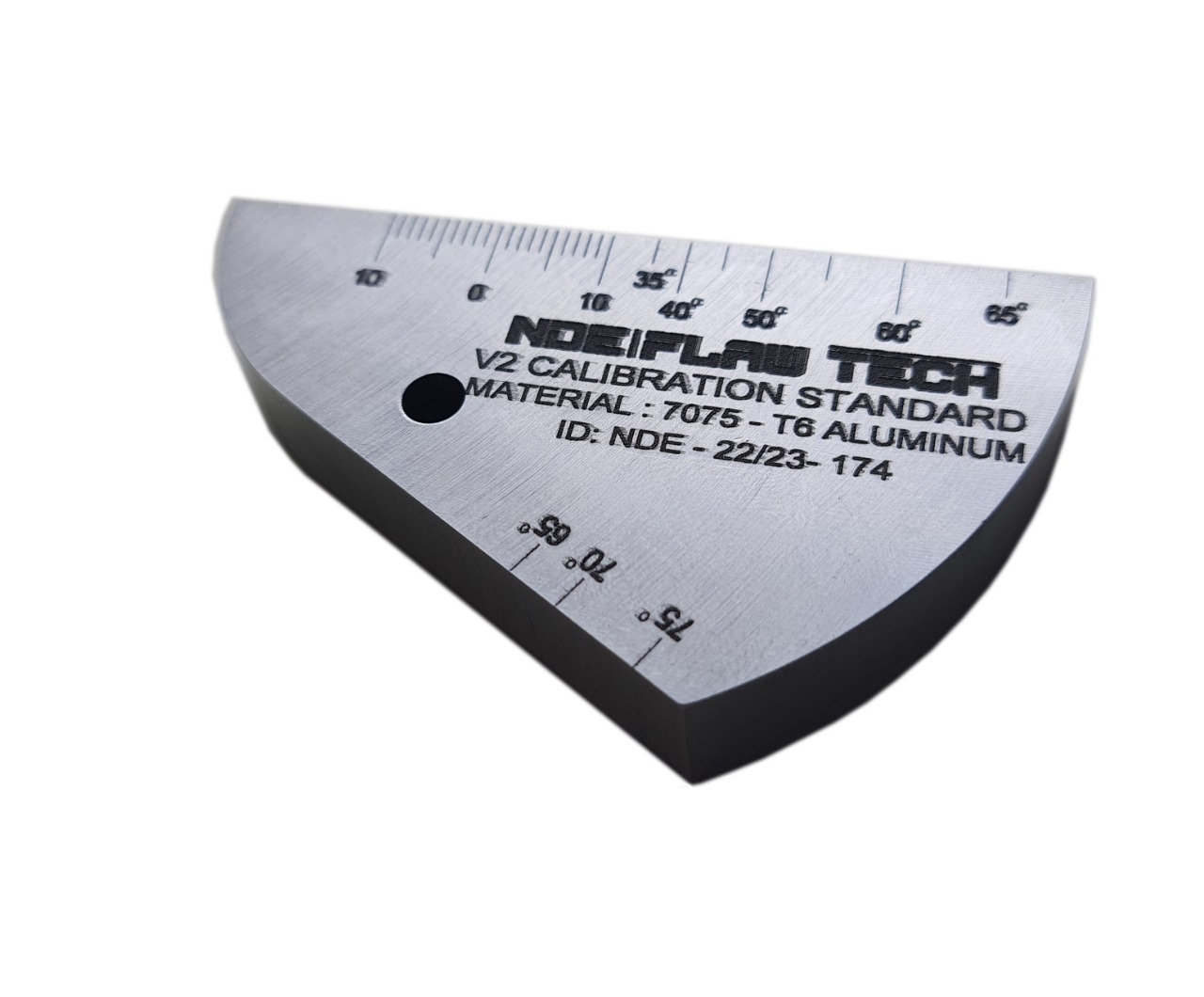
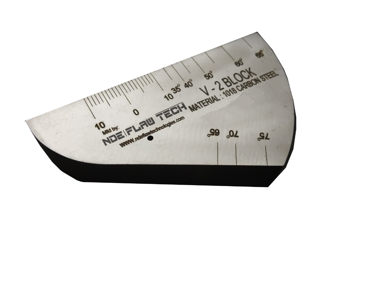
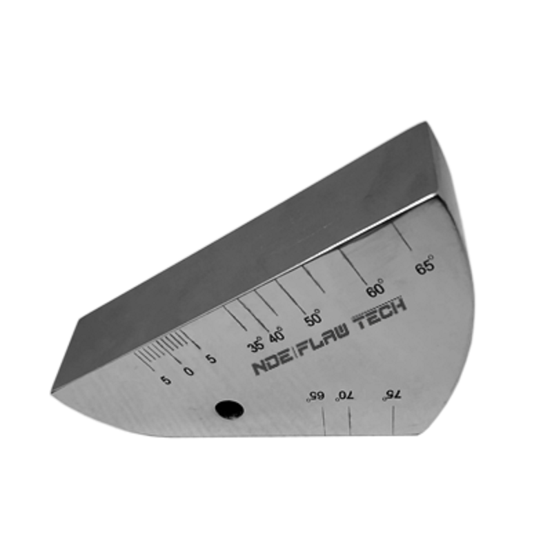
V2 Calibration Test Block
V2 Calibration Test Block The miniature angle-beam is a calibration block that was designed for the US Air Force for use in the field for instrument calibration. The block is much smaller and lighter than the IIW block but performs many of the same functions. The miniature angle-beam block can be used to check the beam angle and exit point of the transducer. The block can also be used to make metal-distance and sensitivity calibrations for both angle and normal-beam inspection setups.
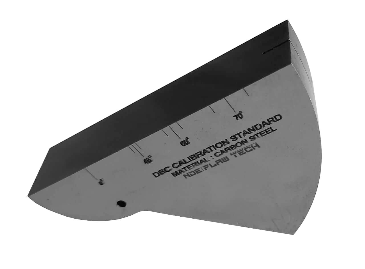
DSC BLOCK
DSC BLOCK A block that closely resembles the miniature angle-beam block and is used in a similar way is the DSC AWS Block. This block is used to determine the beam exit point and refracted angle of angle-beam transducers and to calibrate distance and set the sensitivity for both normal and angle beam inspection setups. Instructions on using the DSC block can be found in the annex of American Society for Testing and Materials Standard E164, Standard Practice for Ultrasonic Contact Examination of Weldments.
API RP 2X Reference Standards LEVEL A BLOCK
API RP 2X Reference Standards LEVEL A BLOCK The reference reflector for establishing the scanning sensitivity must be compatible with the flaw acceptance criteria and provide sufficient sensitivity to ensure detection of the smallest discontinuity of interest. For ultrasonic examination at Level A acceptance criteria, the side of a 1/16-inch (1.6-millimeter) drilled hole provides an excellent reference for use with all transducers. The thickness and length of the block containing the drilled hole should permit evaluation of reference sensitivity at the longest metal path distance anticipated in the actual examination. In addition to the side-drilled holes employed for evaluation of all discontinuities in the body of the weld, two 1/16-inch deep notches are suggested as reference standards to be used in evaluating root reflector in butt or T, K, and Y connections welded from one side only.
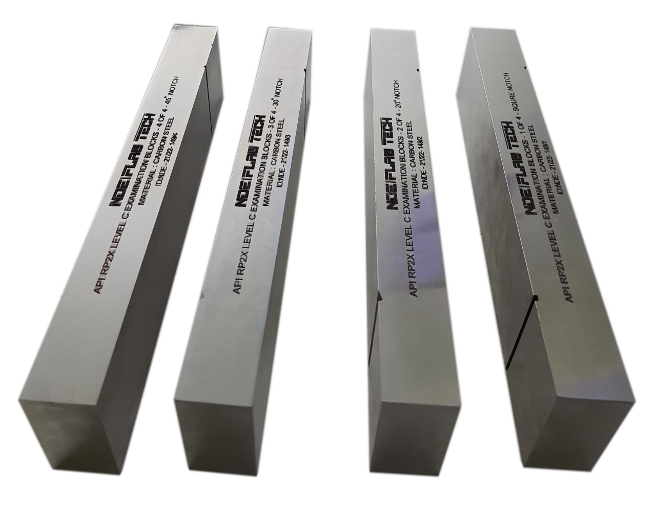
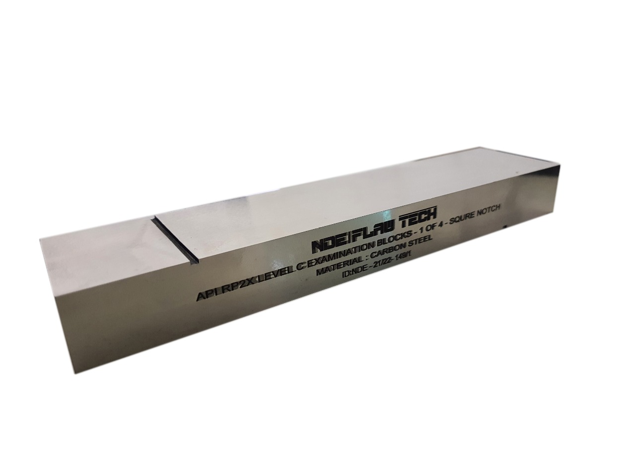
API RP 2X Reference Standards LEVEL C BLOCK
API RP 2X Reference Standards LEVEL C BLOCK The reference block for a Level C examination should contain planar reflectors compatible with the smallest rejectable flaw. One reference block containing a square (buttress) notch and one each with V-notches for 45�degree, 60�degree, and 70�degree orientations should be available for establishing scanning sensitivity for root reflectors. In addition to notches for root reflectors, the side of a 1/16-inch (1.6-millimeter) drilled hole provides an excellent reference for internal reflectors. The response from known size implant reflectors in the operator�s test coupons should be compared with the reflections from the reference blocks to assure that the sensitivity will result in detection of the smallest flaw of interest. Level "C" examination recommended practice 2X (RP 2X). Ultrasonic examination of offshore structural fabrication and guidelines for qualifications of ultrasonic technicians.
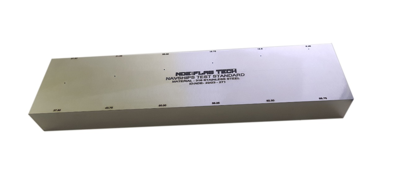
Navships Calibration Test Block
Navships Calibration Test Block Used for distance amplitude correction, sensitivity levels and flaw depth information. MTDs are engraved near both scan edges on one face. In accordance with MIL-STD-271G Figure 9, and NAVSHIPS Specification 0900-006-3010/Section 6. Also known as a "Mare Island block.
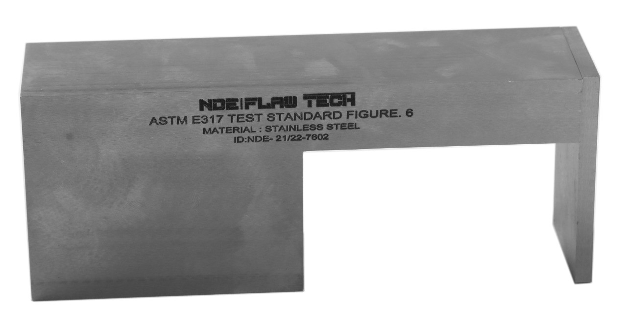
ASTM E317 Test Block Figure 6
ASTM E317 Test Block Figure 6 ASTM E317 resolution block, Figure 6 is used for evaluating the resolution characteristics of ultrasonic pulse-echo systems. ASTM E317 Figure 6. Using this block, adjust the instrument controls to set the system sensitivity to the specified level without excessive loss of resolution. To obtain optimum sensitivity/resolution performance, adjustment of pulse length as well as one or more gain controls will frequently be necessary. If an immersion test, make certain that the search unit is positioned laterally for maximum hole-signal amplitude and aligned for interface perpendicularity. Except for interface peaking, no lower gain may be used thereafter, although higher may be required as described. Resolution, either entry or far surface, is determined as follows. Using the established sensitivity, reposition the search unit over each specified hole in turn to optimize the indication, again making certain that the interface signal is maximized by alignment of the search unit
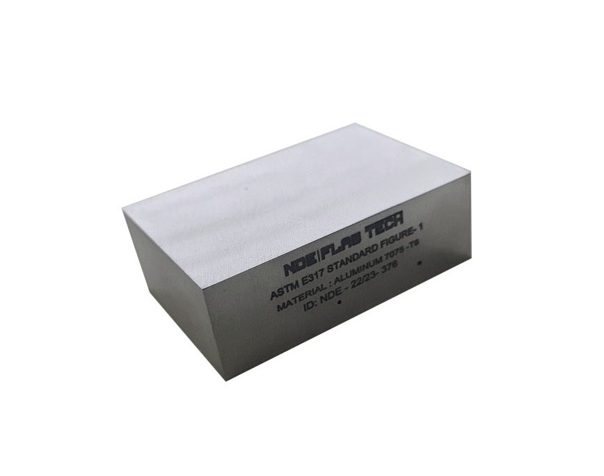
ASTM E317 Test Block Figure 1
ASTM E317 Test Block Figure 1 ASTM E317 horizontal and vertical linearity block, Figure 1 is used for evaluating the horizontal and vertical linearity characteristics of ultrasonic pulse-echo system. Satisfactory for mid-range frequencies and sweep settings on most instruments when the beam is directed through the thickness. Geometry: Two Ø0.047"diameter flat-bottom holes.
A4 Calibration Test Block
A4 Calibration Test Block The miniature angle-beam is a calibration block that was designed for the US Air Force for use in the field for instrument calibration. The block is much smaller and lighter than the IIW block but performs many of the same functions. The miniature angle-beam block can be used to check the beam angle and exit point of the transducer. The block can also be used to make metal-distance and sensitivity calibrations for both angle and normal-beam inspection setups.
K2 Calibration Test Block
K2 Calibration Test Block The miniature angle-beam is a calibration block that was designed for the US Air Force for use in the field for instrument calibration. The block is much smaller and lighter than the IIW block but performs many of the same functions. The miniature angle-beam block can be used to check the beam angle and exit point of the transducer. The block can also be used to make metal-distance and sensitivity calibrations for both angle and normal-beam inspection setups.
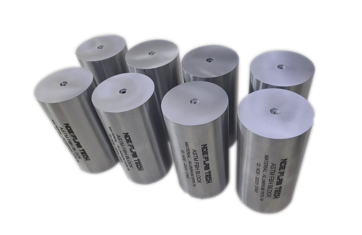
ASTM Area Amplitude Block Set of 8
ASTM Area Amplitude Block Set of 8 ASTM E428 Area Amplitude Calibration Blocks Set of eight flat-bottom hole blocks used to determine the relationship between flaw size and echo amplitude by comparing signal responses. Metal travel distance is 3.000” for all blocks, and FBH diameter ranges from #1 (1/64") to #8 (8/64"). In accordance with E428. Includes our NIST traceable dimensional certification report, ultrasonic inspection report and response plot from Tactic Inc, and the certified material test report. Note that we use a 5.0 MHz quartz transducer for block characterization as required by ASTM E127, Section 11.
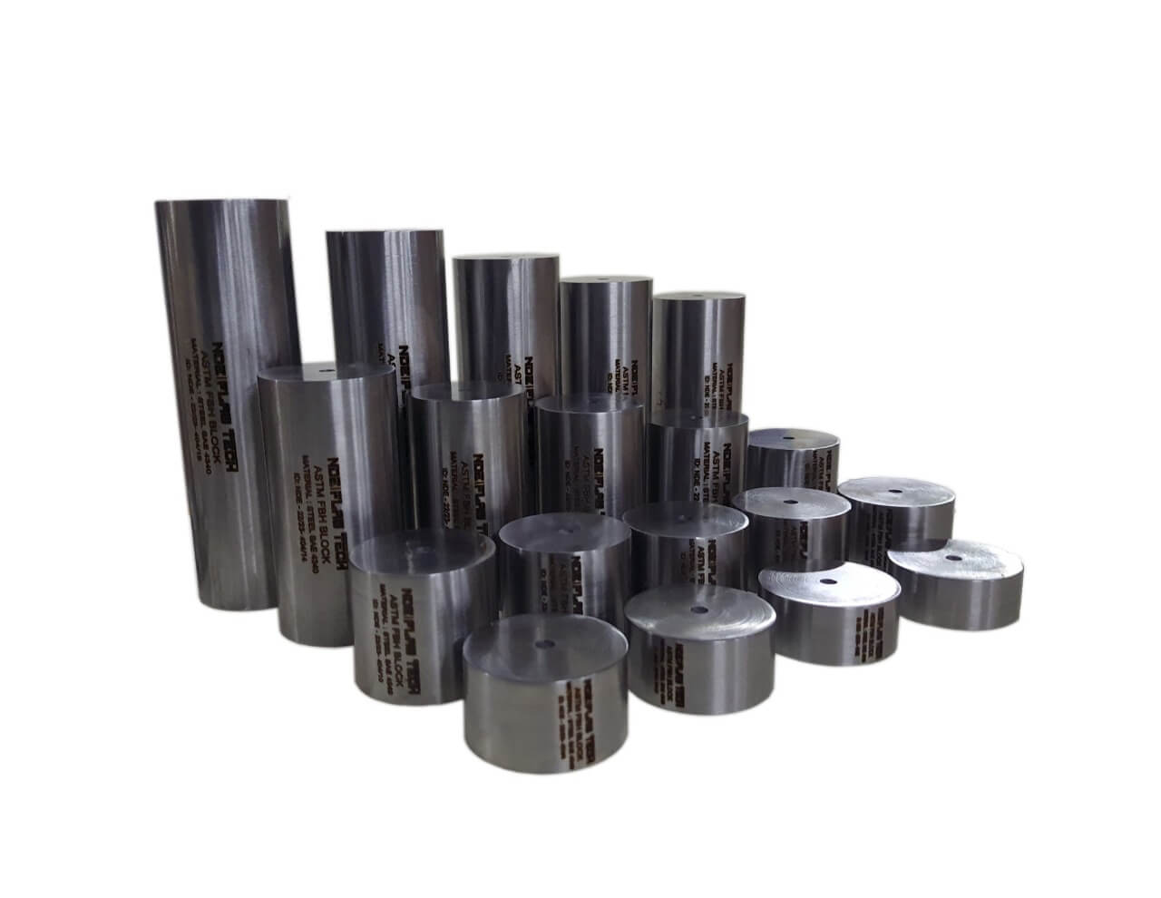
ASTM Distance Amplitude Block Set of 19
ASTM Distance Amplitude Block Set of 19 ASTM E428 Distance Amplitude Calibration Blocks Set of nineteen flat-bottom hole blocks used to determine the relationship between metal travel distance (MTD) and signal amplitude. All blocks have the same size flat-bottom hole and varying MTD. Hole diameter must be specified when ordering (3/64”, 5/64” or 8/64”). In accordance with ASTM E428. Includes our NIST traceable dimensional certification report, ultrasonic inspection report and response plot from Tactic Inc, and the certified material test report. Note that we use a 5.0 MHz quartz transducer for block characterization as required by ASTM E127, Section 11.
ASTM Distance Area Amplitude Block Set of 10
ASTM Distance Area Amplitude Block Set of 10 ASTM E428 Distance Area Amplitude Calibration Blocks Basic set of ten flat-bottom hole blocks used to determine dead zone, sensitivity, distance and area amplitude linearity measurements. In accordance with ASTM E428. Includes our NIST traceable dimensional certification report, ultrasonic inspection report and two response plots from Tactic Inc, and the certified material test report. Note that we use a 5.0 MHz quartz transducer for block characterization as required by ASTM E127, Section 11.
DC Calibration Test Block
DC Calibration Test Block The DC AWS Block is a metal path distance and beam exit point calibration standard that conforms to the requirements of the American Welding Society (AWS) and the American Association of State Highway and Transportation Officials (AASHTO). Instructions on using the DC block can be found in the annex of American Society for Testing and Materials Standard E164, Standard Practice for Ultrasonic Contact Examination of Weldments. AWS-type DC block used for shear wave distance calibration.
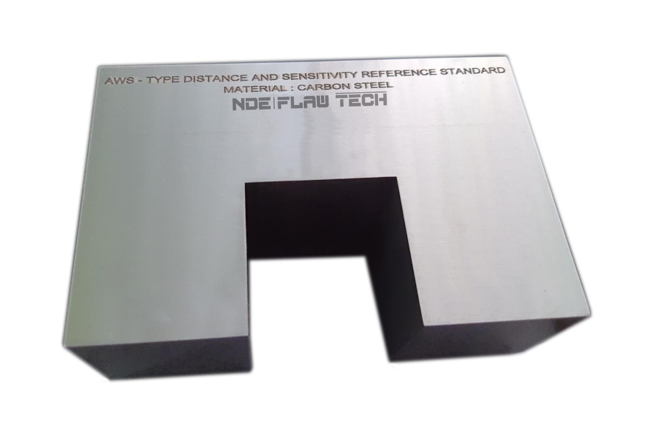
DS Calibration Test Block
DS Calibration Test Block AWS-type block used for longitudinal distance and sensitivity calibration. Contains a 2.0" high section between two 4.0" sections. In accordance with AWS requirements. AWS and ANSI Type DS calibration Block. AWS does not specify a separate metric version of the DS block. The metric block in AWS shows only the metric equivalents to the standard design. Therefore, this one block can be used for both inch and metric requirements.
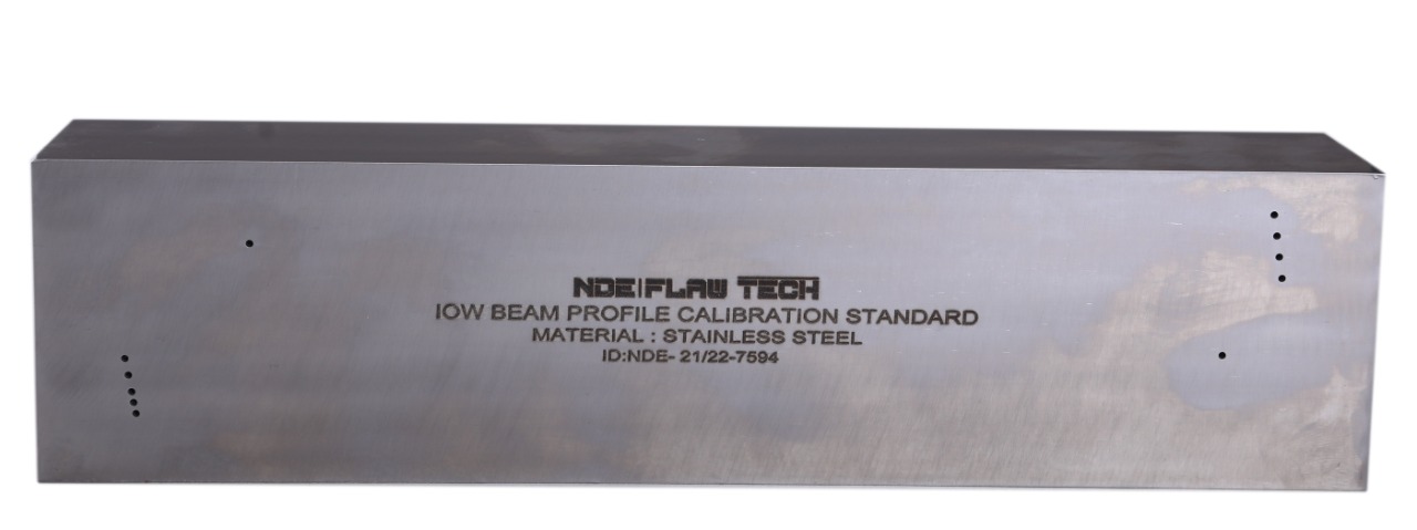
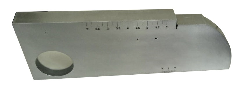
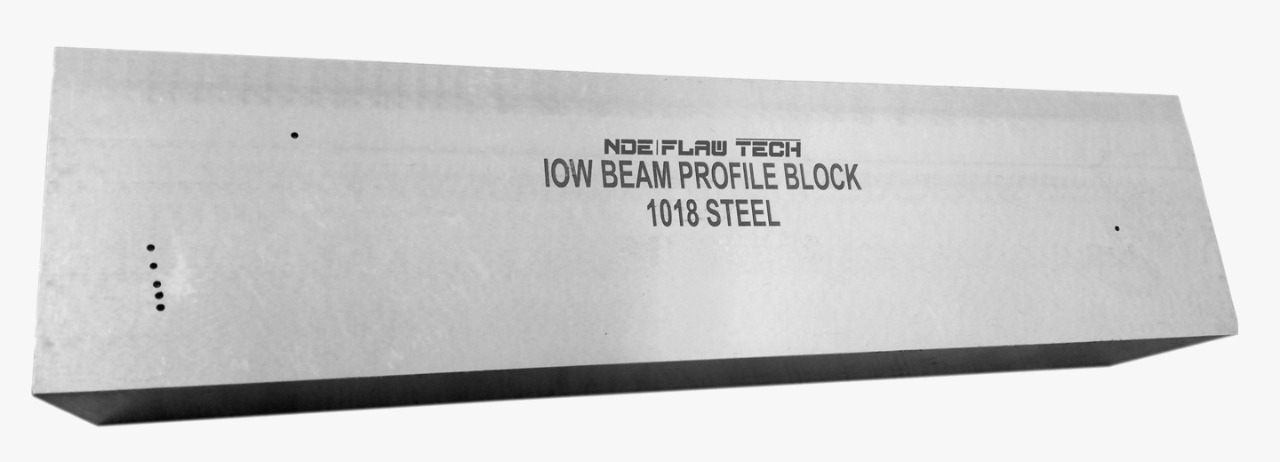
IOW Calibration Block
IOW Calibration Block Used for beam profile measurement of angle beam transducers and measurement of transducer angles. Block used for calibrates resolution check for angle beam transducer, also used for angle beam plotting, to plot beam divergence for shear wave transducer. Analysis of amplitude with respect to exit point is carried out for each angle using data points from depths corresponding to side drilled holes in an IOW block. Graphed and tabulated results are analyzed for trends. This modeling analysis is then compared to actual lab results for refracted angle determination.
A5 Calibration Block
A5 Calibration Block Used for beam profile measurement of angle beam transducers and measurement of transducer angles. Block A5 used for calibrates resolution check for angle beam transducer, also used for angle beam plotting, to plot beam divergence for shear wave transducer. Analysis of amplitude with respect to exit point is carried out for each angle using data points from depths corresponding to side drilled holes in an IOW block (British Standards A5). Graphed and tabulated results are analyzed for trends. This modeling analysis is then compared to actual lab results for refracted angle determination.
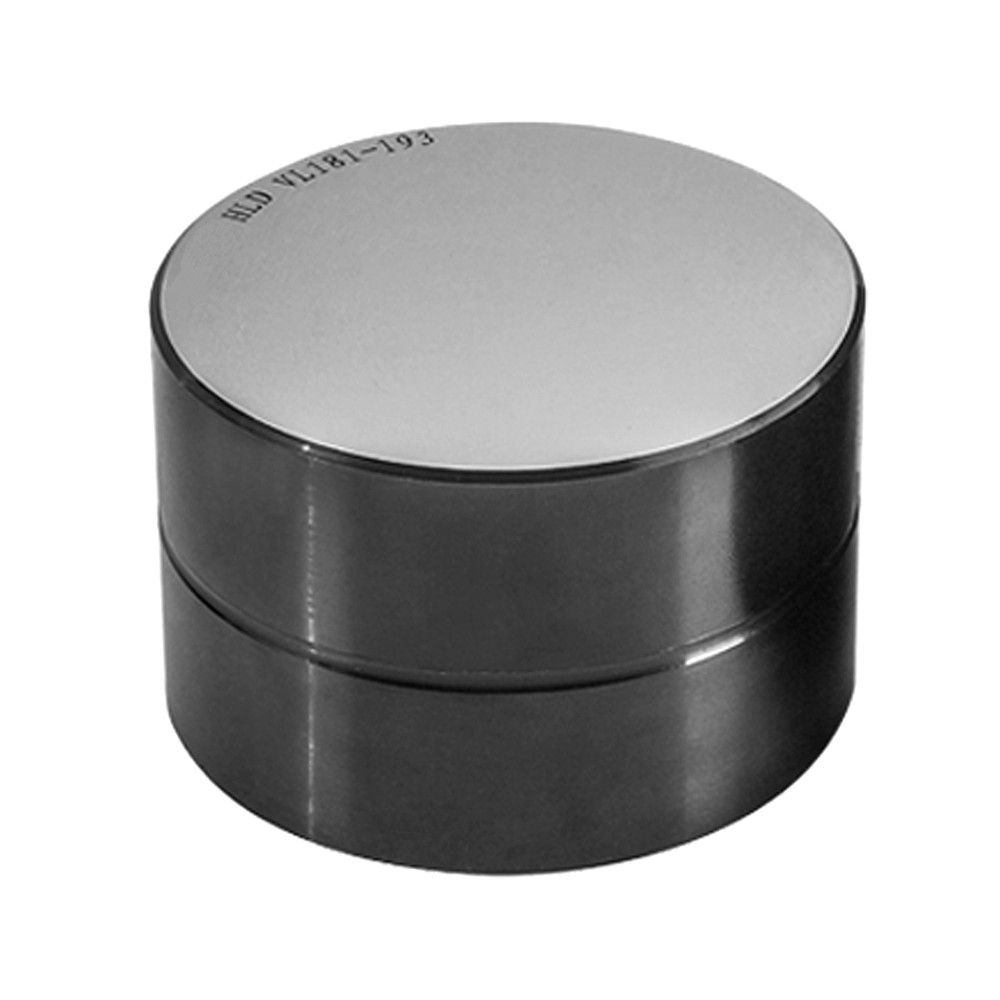
Leeb Hardness Test Blocks
Leeb Hardness Test Blocks Leeb Hardness Test Blocks are used for calibration the hardness testers according to Leeb method. Leeb hardness testing complies to DIN 50156 and ASTM A956. Leeb Hardness Test Block is produced of carbon or alloy steel, has one tested area (operating side) which has the required hardness. The tested area will have several indenter prints as factory final final calibration tests. Also, each calibration block has its identification number on its lateral surface. Measurement range: 530±40 HLD, 630±40 HLD, 790±40 HLD.
V3 Test Calibration Block
V3 Test Calibration Block For calibrating ultrasonic flaw detection equipment in both laboratory and on-site conditions. This block is intended to function as a more compact and light-weight alternative to V1 or IIW-Type Test Blocks.
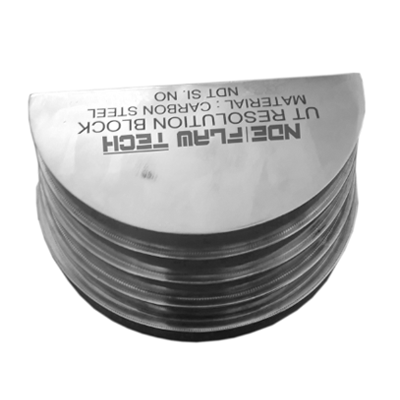
UT Resolutions Calibration Block/A7 BLOCK
UT Resolutions Calibration Block/A7 BLOCK UT Resolution block for Checking shear wave probe resolution. As BS4331 part 3, 1974. Steps of 0.08", 0.12", 0.16" and 0.2"mm.In accordance with BS 2704:1978.
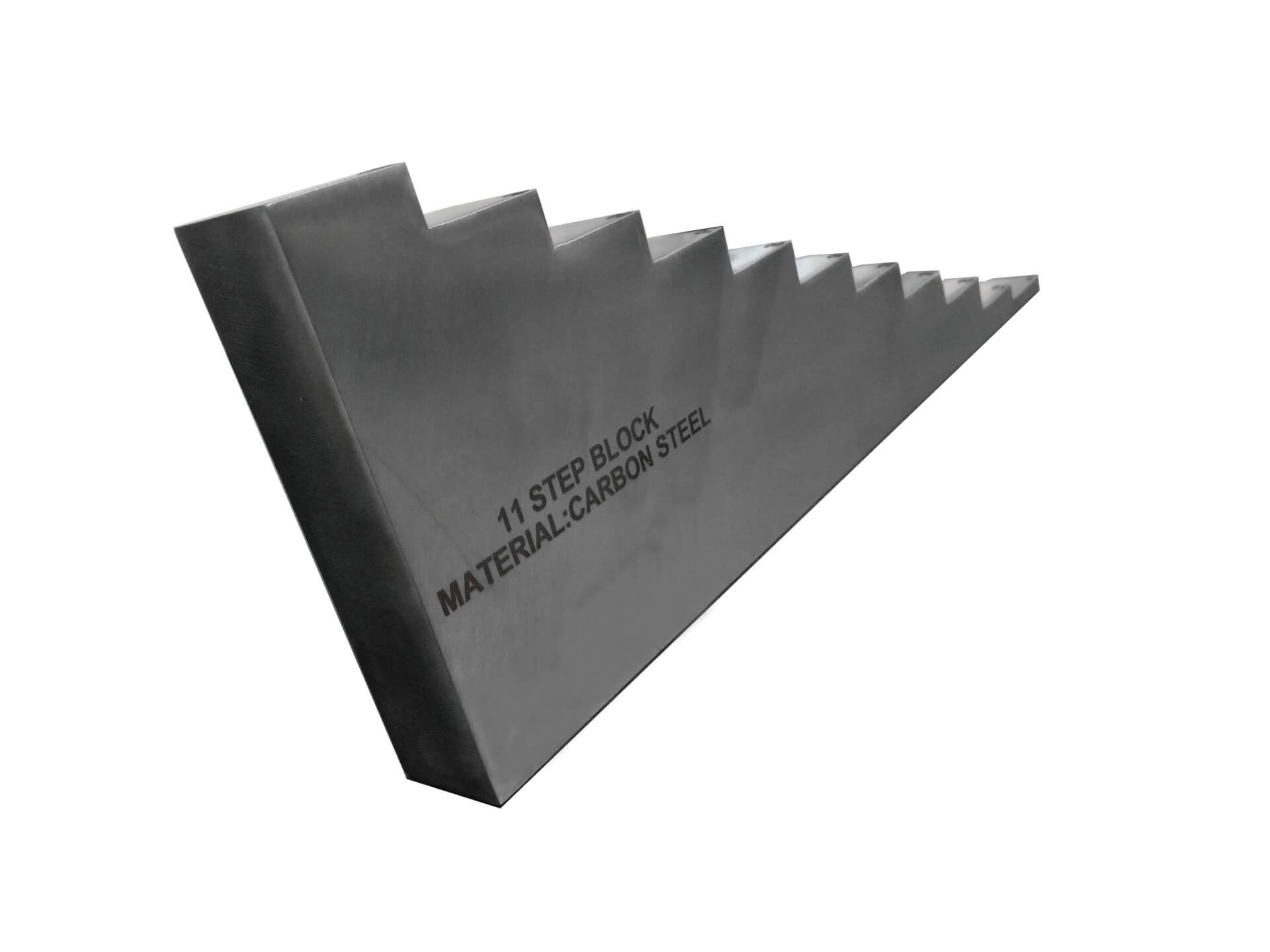
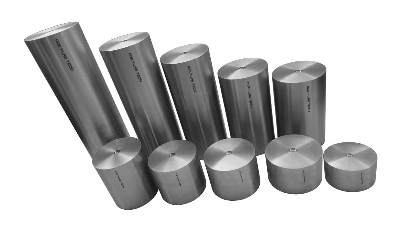
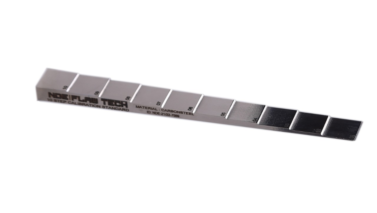
11 Wedge Step Calibration Block
11 Wedge Step Calibration Block Step and tapered calibration wedges come in a large variety of sizes and configurations. Step wedges are typically manufactured with four or five steps but custom wedge can be obtained with any number of steps. Tapered wedges have a constant taper over the desired thickness range.
10 Wedge Step Calibration Block
10 Wedge Step Calibration Block Step and tapered calibration wedges come in a large variety of sizes and configurations. Step wedges are typically manufactured with four or five steps but custom wedge can be obtained with any number of steps. Tapered wedges have a constant taper over the desired thickness range.
8 Wedge Step Calibration Block
8 Wedge Step Calibration Block Step and tapered calibration wedges come in a large variety of sizes and configurations. Step wedges are typically manufactured with four or five steps but custom wedge can be obtained with any number of steps. Tapered wedges have a constant taper over the desired thickness range.
7 Wedge Step Calibration Block
7 Wedge Step Calibration Block Step and tapered calibration wedges come in a large variety of sizes and configurations. Step wedges are typically manufactured with four or five steps but custom wedge can be obtained with any number of steps. Tapered wedges have a constant taper over the desired thickness range.
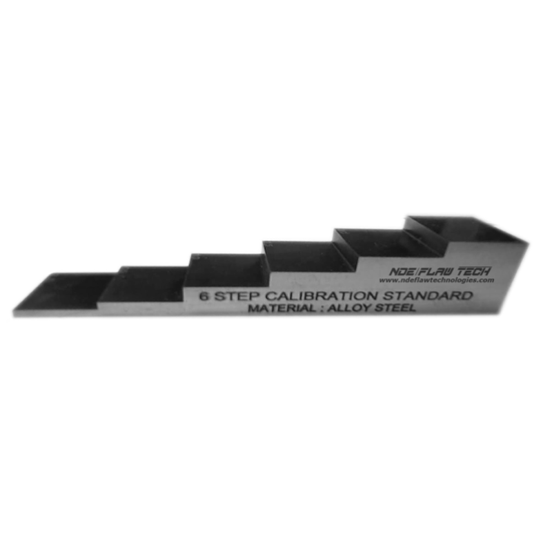
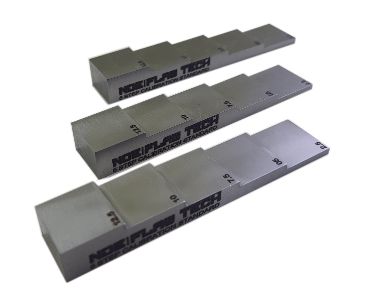
6 Wedge Step Calibration Block
6 Wedge Step Calibration Block Step and tapered calibration wedges come in a large variety of sizes and configurations. Step wedges are typically manufactured with four or five steps but custom wedge can be obtained with any number of steps. Tapered wedges have a constant taper over the desired thickness range.
5 Wedge Step Calibration Block
5 Wedge Step Calibration Block Step and tapered calibration wedges come in a large variety of sizes and configurations. Step wedges are typically manufactured with four or five steps but custom wedge can be obtained with any number of steps. Tapered wedges have a constant taper over the desired thickness range.
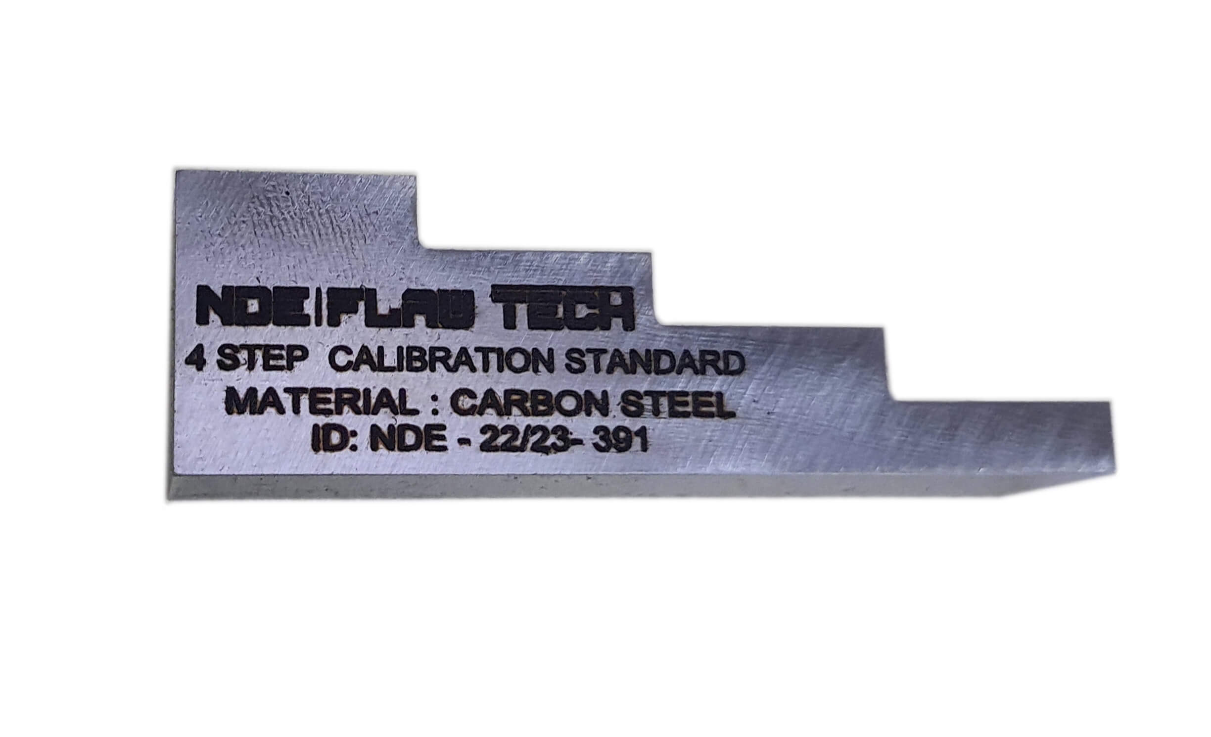
4 Wedge Step Calibration Block
4 Wedge Step Calibration Block Step and tapered calibration wedges come in a large variety of sizes and configurations. Step wedges are typically manufactured with four or five steps but custom wedge can be obtained with any number of steps. Tapered wedges have a constant taper over the desired thickness range.

3 Wedge Step Calibration Block
3 Wedge Step Calibration Block Step and tapered calibration wedges come in a large variety of sizes and configurations. Step wedges are typically manufactured with four or five steps but custom wedge can be obtained with any number of steps. Tapered wedges have a constant taper over the desired thickness range.
PDI Alternative ASME Calibration Test Block
PDI Alternative ASME Calibration Test Block PDI Alternative ASME blocks are manufactured in accordance with the requirements of the Performance Demonstration Initiative (PDI) Procedure No. PDI-UT-1, Rev. C, Fig. 4 (Ferritic) and PDI-UT-2, Rev. C, Fig. 4 (Austenitic). These cover the generic procedures for the ultrasonic examination of both ferritic and austenitic pipe welds. The blocks offer an economical alternative to fabricating multiple curved calibration blocks (pipe sections) in numerous diameters and wall thicknesses.
PDI Alternative ASME Calibration Test Block 3 Set
PDI Alternative ASME Calibration Test Block 3 Set PDI Alternative ASME blocks are manufactured in accordance with the requirements of the Performance Demonstration Initiative (PDI) Procedure No. PDI-UT-1, Rev. C, Fig. 4 (Ferritic) and PDI-UT-2, Rev. C, Fig. 4 (Austenitic). These cover the generic procedures for the ultrasonic examination of both ferritic and austenitic pipe welds. The blocks offer an economical alternative to fabricating multiple curved calibration blocks (pipe sections) in numerous diameters and wall thicknesses. The blocks are normally supplied in sets of 3 individual blocks; one in A516 Grade 70 Steel, one in Type 304/304L Stainless Steel, and one in Type 316/316L Stainless Steel. Overall block dimensions - 2.000" wide x 2.250" tall x 10.000" long.
 EN 12223.jpeg)
Calibration Block No.1
Calibration Block No.1 Calibration Block No.1 are used to calibrate instruments for both angle beam and normal incident inspections. Some of their uses include setting metal-distance and sensitivity settings, determining the sound exit point and refracted angle of angle beam transducers, and evaluating depth resolution of normal beam inspection setups.
.jpeg)
Calibration K1 Block
Calibration K1 Block K1 Block are used to calibrate instruments for both angle beam and normal incident inspections. Some of their uses include setting metal-distance and sensitivity settings, determining the sound exit point and refracted angle of angle beam transducers, and evaluating depth resolution of normal beam inspection setups.
Monolithic – Flat Bottom 9 Hole Block
Monolithic – Flat Bottom 9 Hole Block Material: • Carbon Fiber • 3” x 6” x 0.25” T Specifications: • 9 Flat Bottom Holes (FBH) • 3 – 0.125” Diameter @ 0.025”, 0.063” and 0.125” Depth. • 3 – 0.25” Diameter @ 0.025”, 0.063” and 0.125” Depth. • 3 – 0.50” Diameter @ 0.025”, 0.063” and 0.125” Depth. • Flaws: Total of 9 FBHs • Specimens will be identified with a unique serial number Final Documentation: • Certificate of Conformance, “As Built” CAD drawings and Test Sheets
Cored – Impact Damage Block
Cored – Impact Damage Block Material: • 0.25” Carbon Fiber Laminate each side • 0.75” Foam Core • 3” x 6” x 1.3” T Specifications: • Carbon Fiber Laminate with Foam Core • Flaw: Impact Damage • Specimens will be identified with a unique serial number Final Documentation: • Certificate of Conformance, “As Built” CAD drawings and Test Sheets
Monolithic – Impact Damage w/Fiber Break Block
Monolithic – Impact Damage w/Fiber Break Block Material: • Carbon Fiber • 3” x 6” x .25” T Specifications: • Solid Carbon Fiber Laminate • Flaws: Impact Damage and Fiber Break • Specimens will be identified with a unique serial number Final Documentation: • Certificate of Conformance, “As Built” CAD drawings and Test Sheets
Cored – Disbond & Delamination Block
Cored – Disbond & Delamination Block Material: • 0.10” Carbon Fiber Laminate each side • Foam Core • 6” x 6” x 1.2” Specifications: • Carbon Fiber with Foam Core • Flaws: Core Dis-bond and Delamination • Specimens will be identified with a unique serial number Final Documentation: • Certificate of Conformance, “As Built” CAD drawings and Test Sheets
22 Ply – 11 Step Block w/ Teflon Voids
22 Ply – 11 Step Block w/ Teflon Voids Material: • Carbon Fiber • 2.75” x 3” x 12” Specifications: • 11 Step Block with Teflon Inserts • 10 – 1” wide steps and 1- 2” wide Step. • Steps at: 0.25”, 0.50”, 0.75”, 1”, 1.25”, 1.5”, 1.75”, 2”, 2.25, 2.5, 2.75” • Step 1 has one .5”x .5” Teflon inserts • Steps 2-11 have a both a .25” x .25” and .5 x .5” inserts • Flaws: Total of 21 Teflon Inserts • Specimens will be identified with a unique serial number Final Documentation: • Certificate of Conformance, “As Built” CAD drawings and Test Sheets